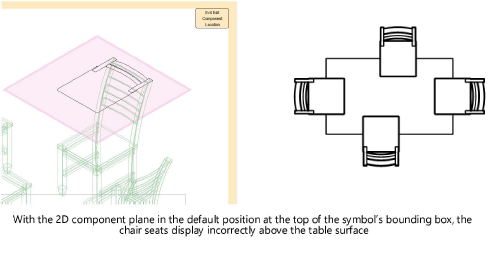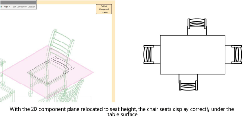
All graphics of a 2D component must reside on a single plane. When creating 2D components, by default the 2D component plane is placed on the 3D bounding box face nearest the component view. For example, the right 2D view is placed on the right face of the bounding box. When the 2D component plane remains in this default position, it automatically adjusts to 3D changes that alter the size of the bounding box.
Sometimes, however, it is necessary to move a 2D component plane from the face of a bounding box. For example, if the Top component of a dining chair is in the default location on the top face of the bounding box, the seat would display above the dining table surface. This creates the appearance of incorrect stacking order.
To relocate a 2D component:
1. If not already in object editing mode, right-click on the resource in the Resource Manager or on the object instance in the drawing, and select Edit 2D Components from the context menu (see Creating 2D components for symbol definitions and plug-in objects).
2. From the Component Edit palette, select the component to Edit.
3. From the Component Edit palette, click Edit Component Location. The nested editing mode displays the 2D component plane location.
4. Click the 2D component and move the 2D component plane to the desired location. The plane is constrained to move along its perpendicular axis and within the extents of the bounding box. You may rotate the view as necessary to effect the change.
5. Click again to place the plane.


~~~~~~~~~~~~~~~~~~~~~~~~~