 Inserting a photometric grid Inserting a photometric grid
 Tool |
Tool set |
Photometric Grid
|
Lighting |
The photometric grid is a is a three-click rectangular object, and can be inserted in Center-line Placement mode or Edge Placement mode. The grid can be tilted, accounting for sloped or raked stages.

Mode |
Description |
Center-line Placement |
Click once, and then again, to define the length through the center of the grid. Click again to specify the grid width. |
Edge Placement |
Click once, and then again, to define the length along the edge of the grid. Click again to specify the grid width. |
Preferences |
Sets the default preferences for the photometric grid |
To insert a photometric grid:
1. Ensure that each lighting instrument contributing to the illumination is focused.
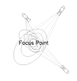
The light beams do not have to be drawn for calculations to be made.
2. Click the tool and a placement mode.
3. Click in the drawing area to insert the photometric grid.
The first time you use the tool in a file, a properties dialog box opens. Set the default properties. The properties can be edited from the Object Info palette.
![]() Click
to show/hide the parameters.
Click
to show/hide the parameters.
After placing the photometric grid, set the grid’s Z value from the Object Info palette; illumination values vary depending on the grid’s elevation.
~~~~~~~~~~~~~~~~~~~~~~~~~
