Adding
Plants to the DesignAdding
Plants to the Design
Adding
Plants to the DesignAdding
Plants to the DesignPlant placement in the Vectorworks Landmark program is very flexible. Generally, plants are defined first, and then placed; plant parameters are set by the definition, but if necessary, certain parameters can be changed in the Plant Settings dialog box before placement, or in the Object Info palette after placement. This allows variations of the same plant definition, which is an essential part of a landscape designer’s workflow. Another way of placing plants is to place “generic” plants from the default content, and create plant definitions for them later.
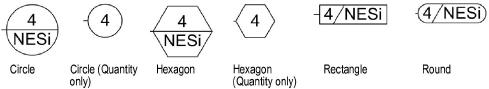
In addition to the appearance and parameters defined for plants, the Plant tool can place plants in several configurations, from single plants to arrays of plants. When setting parameters after placement, an array of plants is considered to be a single “plant” in the Object Info palette. Plants can also created by drawing a polyline and then selecting the Create Objects from Shapes command (see Creating Objects from Shapes).
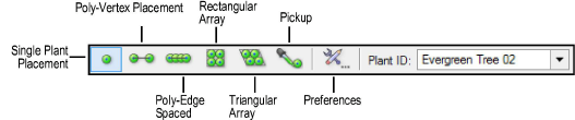
Mode |
Description |
Single Plant Placement |
Places a single specified plant at each mouse click
|
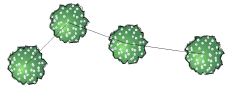
Poly-Vertex Placement |
Places plants at each clicked polygon vertex
|
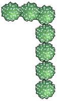
Poly-Edge Spaced |
Places plants along the drawn polygon at the Spacing distance specified in the definition or settings
|
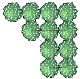
Rectangular Array |
Fills the drawn polygon with plants in a rectangular array at the Spacing distance specified in the definition or settings
|
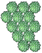
Triangular Array |
Fills the drawn polygon with plants in a triangular array at the Spacing distance specified in the definition or settings
|
Pickup |
Sets the default plant settings to match those of a selected existing plant |
Preferences |
Opens the Plant Settings dialog box, for specifying the plant to place, its placement options, and its definition |
Plant ID |
Selects a plant for placement by its ID (Plant Symbol Name) |

To place plants on the drawing:
1. Click the Plant tool from the Site Planning tool set and select the plant to place.
The Plant Settings dialog box opens automatically if there are no plants in the Resource Browser. Otherwise, click Preferences from the Tool bar to select the plant to place, and specify the plant settings if they are different from the definition. The plant settings are described in the following sections.
The plant to place can also be selected by its plant symbol name from the Plant ID list on the Tool bar. The plant resources in the active drawing display alphabetically at the top of the list; the remaining plants are from the default content resources.
Double-click a plant from the Resource Browser to activate the Plant tool and place the selected plant.
The Plant tool uses these settings until they are changed again by selecting a different plant ID from the Tool bar, clicking Preferences from the Tool bar, or until Pickup mode is selected, which changes the default settings to those of a selected existing plant.
2. Select the plant placement mode from the Tool bar.
3. Depending on the placement method selected, either click in the drawing to place a single plant, or draw a polygon. As the Plant tool is clicked in the drawing, a preview of the plant spread is displayed to help with plant placement.
The Plant tool parameters are retained so that the successive placement of plants is easily accomplished.
Each pane of the plant settings is described in the following sections. As the parameters are defined, the preview dynamically displays the plant appearance.
Do not be confused by the similar appearance of the Plant Settings dialog box and the Edit Plant Definition dialog box; keep in mind that the plant definition parameters define the default plant settings. The default plant settings can be changed at placement if needed, allowing for variations of the same plant definition. Default plant settings that do not require editing can be left as defined by the plant definition.
The Definition pane can be used to select the plant definition for placement by the Plant tool. From any pane, you can also edit the plant definition parameters or create a duplicate of the plant definition, as described in Creating Plant Definitions.
Click to show/hide the parameters.
The Insertion Options pane displays the default plant insertion settings from the plant definition. To override the plant definition parameters, select the parameter check box and enter the custom value. In addition, if the plant should be included in plant report worksheets, select On Plant List.
Click to show/hide the parameters.
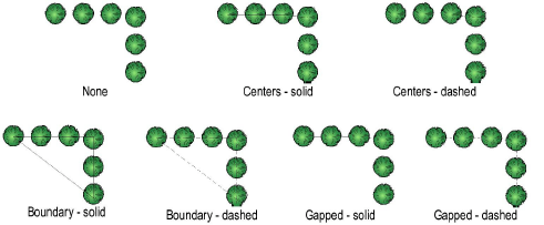
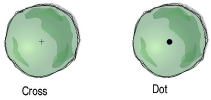
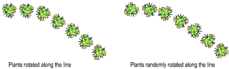
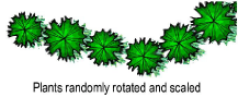
Select plant display parameters on the Annotation pane.
Click to show/hide the parameters.
The Render pane displays the default render settings from the plant definition. The Use Plant Definition settings indicate that the plant definition render settings apply; see Plant Definition: Render Pane. To override the plant definition parameters, select the Custom outline and massing option, and/or select the No Shadow, Use Document Preference Settings, or Custom shadow setting.
Set the display of the plant ID tags on the Tag pane. To create a custom plant tag, see Creating a Custom Plant Tag. After creation, the plant tag’s appearance can be modified via the Plant Settings Tag pane, Object Info palette, tag class settings, and the control point locations on the drawing (see Plant Tag Appearance).
Click to show/hide the parameters.
The Schedule pane displays the default schedule settings from the plant definition; see Plant Definition: Schedule Pane. To override the plant definition parameters, select the parameter check box and enter the custom value.
~~~~~~~~~~~~~~~~~~~~~~~~~
![]()