Inserting multicablesInserting multicables
Mode |
Tool |
Tool set |
Modes for the Polyline tool |
Multicable
|
Lighting |
Multi-circuit cables, also known as multicables, carry power from power distribution racks and dimmer racks to the lighting instruments, projectors, and other devices. Multicables include break in and break out parts, which attach to the cable and allow power to enter the multicable and to be distributed from the cable.
Some of the multicable parameters that are tedious to manually assign can be automatically assigned, as described in Assigning circuit information and Placing break out labels.
Multicable break outs have special labels; entering some of the multicable and break out information can be accomplished from the Object Info palette of the associated label. See Placing break out labels.
To insert a multicable:
1. Click the tool and mode.
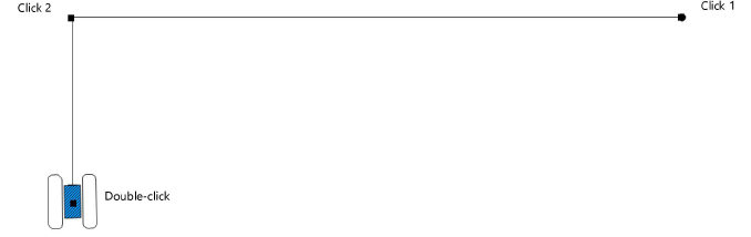
2. Click to place the start of the cable, and draw the cable polyline, clicking at each vertex. Double-click to finish drawing the cable.
The first time you use the tool in a file, a properties dialog box opens. Set the default properties.
After placement, the cable path can be adjusted with the Reshape tool. The properties can be edited from the Object Info palette.
![]()
![]() Click
to show/hide the parameters.
Click
to show/hide the parameters.
Parameter |
Description |
Cable Run ID |
Names the cable run, which is useful for labels, schedules, and other worksheets |
Rack ID |
Names the rack to which the cable connects |
Box ID |
Provides the distribution box name |
Port ID |
Names the port where the cable plugs in |
Loom ID |
Names the loom or bundle that includes the cable |
Tape Color Code |
Identifies the cable with a color code, which can be used to label racks and breaks |
Cable Type |
Select the type of multicable |
Cable Path Length |
Displays the total length of cable required for the cable run; the label displays how much extra (unused) cable is present |
Total Vertical Distance |
If the cable needs to travel vertically (to go around an opening, for example), the vertical distance is set for each part. This parameter displays the total vertical distance required. |
Calculate Parts |
Automatically determines the parts, or segments, of cable lengths needed to make up the cable run, using the fewest possible number of connections. The drawn cable is divided into parts, up to a total of nine parts, according to the available cable lengths in stock; each part displays with its own data. |
Stock Lengths |
Displays the available lengths of cable as set in the cable preferences |
Part __ |
Displays the length of each cable part |
Part __ Vert Dist |
Displays the vertical distance, if any, required for the part to travel around obstacles |
Part __ Loom ID |
Identifies the loom or bundle that includes this section of cable |
Cable Break __ ID |
Identifies the name of any cable break |
Part Total |
Displays the total length of cable used when all the parts are added |
Part Total Is |
Displays the extra length of cable available |
Break Out Type |
Select the break out type |
Adapter __ |
Select the type of adapter |
Adapter __ Count |
Indicates how many adapters are present |
Break Out Length |
Specifies the length of the break out cable |
Staggered |
Indicates that the break out has circuit cables at different lengths |
Staggered Lengths |
When the break out is staggered, specifies the length of each circuit cable |
Break Out Only |
Hides the multicable, displaying only the break out; when this option is selected, the multicable is not counted in reporting worksheets |
Draw Break Out Range |
Displays the break out range coverages on the cable
|
Break Out Location |
Provide a name for the break out location for informational purposes |
Circuit __ |
Provide the circuit information for each break out circuit. If the circuit fields are not displayed, select Show Break Outs from the Object Info palette. |
Break In Type |
Select the break in type |
Break In Length |
Specifies the length of the break in cable |
Break In Location |
Provide a name for the break in location |
Break In Circuit __ |
Provide the patch information for each break in circuit. If the circuit fields are not displayed, select Show Break Ins from the Object Info palette. |
Max Amperage |
Specifies the maximum amperage for the power source |
Voltage |
Specifies the cable voltage provided by the power source; this value is used in the voltage drop calculation. Select Other if the provided voltage is not listed. When Other is selected for the Voltage, specify the power source voltage |
Wire Gauge |
Select the cable wire size |
Voltage Data |
Displays the voltage drop calculations and data. ● Voltage Drop Formula: displays the formula used to calculate the voltage drop. ● Voltage Delivered: displays the voltage delivered at the end of the cable (after accounting for the voltage drop). ● Voltage Drop: displays the amount of voltage lost to cable resistance. ● Percentage Drop: displays the percentage of voltage lost from the cable run. ● CM Value: displays the Circular Mill (CM) value assigned to the cable based on the wire gauge. If the voltage data are not displayed, select Show Voltage Drop Calculation from the Object Info palette. |
Inventory ID |
Enter an optional inventory code for the cable |
User Field __ |
Adds optional notes or comments about the cable, useful for reporting purposes. Field 3 is for entering a number only. |
Display on Drawing |
Enables the display of cable information on the drawing
|
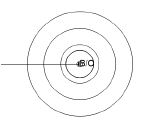
Mark Connections |
Displays a marker and the cable length information where a cable connection is located; the multi head symbol may obscure the connection marker, but the multi head symbol location can be adjusted
|
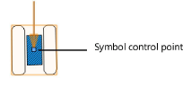
Display Multi Head |
Adds a symbol at the end of the cable, to represent the break out connectors. Select the symbol to display from the Multi Head Symbol list. Adjust the location of the symbol by moving its control point; restore the symbol to its default position, and prevent it from being moved, by selecting Lock Multi Head Symbol to Standard Position.
|
Lock Labels to Standard Position |
Restores text labels to their default positions, and prevents them from being moved |
Label Text Size |
Sets the text font size for the cable’s labels |
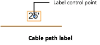
Display Length |
Displays the cable length in the label along the cable path |
Display Length Trailer |
Adds text to the cable path label, after the length value |
Horizontal Length Text |
Adjusts the cable path label to match the angle of the cable part; deselect the option to keep the text horizontal |
Display Start Label |
Adds a Cable Run ID label at the start of the cable run; enter the text to display. The label has its own control point for adjusting its location. |
Display End Label |
Adds a Cable Run ID label at the end of the cable run; enter the text to display. The label has its own control point for adjusting its location. |
Display Break Ins |
Adds a break in label, displaying the circuit information; set the break in label text size |
Display Break Outs |
Adds a break out label, displaying the circuit information; set the break out label text size |
Lock Break Outs and Break Ins to Standard Positions |
Restores break in and break out text labels to their default positions, and prevents them from being moved |
Show / Hide Parameters |
Shows or hides the specific parameters in the Object Info palette |
Show Break Ins |
Displays break in circuit parameters in the Object Info palette |
Show Break Outs |
Displays break out circuit parameters in the Object Info palette |
Show Voltage Drop Calculation |
Displays voltage data in the Object Info palette |
Opens the Classes dialog box, to specify class naming for the cable labels. This allows the labels to be set to visible, grayed, or invisible. Use the suggested standard class, select a class from the list of classes present in the drawing, or create a new class. Select <Multicable Class> to place the labels in the same class as the multicable. ● Class Prefix: Specifies an optional default root class naming standard for the cable labels; click Use Standard Classes to begin all label class names with the prefix, so that they are sorted together. ● Use Standard Classes: Sets the class name for the label to the default suggested standard name, using the Class Prefix if there is one. ● Labels: Specifies the class name standard to use for the cable labels. |
|
Load Information |
A cable is considered a distributed load in Braceworks calculations; if the cable is inserted parallel to a structural element, it is considered to be a load on that structure. Load information is used for Braceworks calculations and reports (Braceworks required). |
Include in Calculations (Braceworks required) |
Includes the cable in Braceworks calculations; deselect to exclude the object from participating in structural calculations |
Load Group Name |
The load category is always Cable for cable objects |
Load ID |
Enter a unique ID for the load for informational use in reports |
Load Name |
Identifies the object in load calculations |
Distributed Weight |
Enter the distributed weight of the cable; changes here also affect the Total Weight value |
Total Weight |
Enter the total weight of the object |
Vertex parameters |
Edits the vertices of the path object that the cable is based upon; see Editing vertex-based objects |
~~~~~~~~~~~~~~~~~~~~~~~~~
Assigning multicable information
Selecting, refreshing, and converting cables
Associating loads with rigging objects