 Inserting
a distributed loadInserting
a distributed load
Inserting
a distributed loadInserting
a distributed loadMode |
Tool |
Tool set |
Distributed Load
|
Insert Load
|
Rigging |
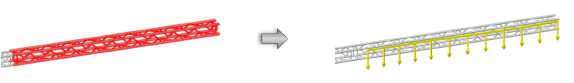
To insert a distributed load:
1. Click the tool and mode.
2. Do one of the following:
● To use a saved set of load properties, click Load Settings on the Tool bar and select the load set.
● If not using a saved load set, specify the Load Category; select either Distributed Weight or Total Weight mode and enter the load’s Weight. If entering the distributed weight, enter values with a slash between the weight and the distance (500/10 indicates 500 pounds per 10 feet of length, for example).
3. Move the mouse to the structural element where the distributed load is to be hung.
Valid connecting structures are highlighted.
4. Click to set the load object’s start point.
5. Click to set the end of the segment and the beginning of the next. Continue drawing segments in this manner until the load object is complete. Double-click to finish creating the load object. The distributed load polyline cannot extend beyond the structural element.
The distributed load is placed at the centerline of the structural element.
In Top/Plan view, the distributed load label displays. It can be moved by clicking and dragging the label control point.
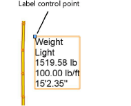
The distributed load properties can be edited from the Object Info palette.
![]() Click
to show/hide the parameters.
Click
to show/hide the parameters.
Command |
Path |
Add Distributed Load at Selection |
Braceworks |
The Insert Distributed Load at Selection command is available for Vectorworks Spotlight software but is not present in the Spotlight workspace. It can be added to the Spotlight workspace (see Customizing workspaces).
If the length of a distributed load is not critical, a distributed load can be added automatically to the structural elements in the drawing.
To add a distributed load automatically:
1. Select the structural element where the distributed load will be placed. When more than one structure is selected, a distributed load is placed on each one.
Select the system to easily select more than one structural element, and automatically add the same load to each.
2. Select the command.
The Load Settings dialog box opens, for Creating and selecting load sets. Select a load set, or enter load parameters and select the <Active Settings> set.
A distributed load is placed along the length of each structural element.
~~~~~~~~~~~~~~~~~~~~~~~~~

